
A cam is a rotating machine element which gives
reciprocating or oscillating motion to another element known
as follower. The cam and the follower have a line contact
and constitute a higher pair. The cams are usually rotated at
uniform speed by a shaft, but the follower motion is predetermined
and will be according to the shape of the cam.
The cam and follower is one of the simplest as well as one
of the most important mechanisms found in modern
machinery today. The cams are widely used for operating
the inlet and exhaust valves of internal combustion engines,
automatic attachment of machineries, paper cutting machines,
spinning and weaving textile machineries, feed mechanism
of automatic lathes etc.
Classification of Followers:
The followers may be classified as discussed below :
1. According to the surface in contact. The followers,
according to the surface in contact, are as follows :
(a) Knife edge follower. When the contacting end of
the follower has a sharp knife edge, it is called a
knife edge follower, as shown in Fig. 20.1 (a). The
sliding motion takes place between the contacting
surfaces (i.e. the knife edge and the cam surface). It
is seldom used in practice because the small area of
contacting surface results in excessive wear. In knife
edge followers, a considerable side thrust exists
between the follower and the guide.
(b) Roller follower. When the contacting end of the follower is a roller, it is called a roller
follower, as shown in Fig. 20.1 (b). Since the rolling motion takes place between the
contacting surfaces (i.e. the roller and the cam), therefore the rate of wear is greatly reduced.
In roller followers also the side thrust exists between the follower and the guide. The
roller followers are extensively used where more space is available such as in stationary
gas and oil engines and aircraft engines.
(c) Flat faced or mushroom follower. When the contacting end of the follower is a perfectly
flat face, it is called a flat-faced follower, as shown in Fig. 20.1 (c). It may be noted that
the side thrust between the follower and the guide is much reduced in case of flat faced
followers. The only side thrust is due to friction between the contact surfaces of the follower
and the cam. The relative motion between these surfaces is largely of sliding nature but
wear may be reduced by off-setting the axis of the follower, as shown in Fig. 20.1 (f ) so
that when the cam rotates, the follower also rotates about its own axis. The flat faced
followers are generally used where space is limited such as in cams which operate the
valves of automobile engines.
Note : When the flat faced follower is circular, it is then called a mushroom follower.
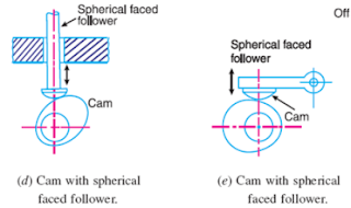
(d) Spherical faced follower. When the contacting end of the follower is of spherical shape,
it is called a spherical faced follower, as shown in Fig. 20.1 (d). It may be noted that when
a flat-faced follower is used in automobile engines, high surface stresses are produced. In
order to minimise these stresses, the flat end of the follower is machined to a spherical
shape.

2. According to the motion of the follower. The followers, according to its motion, are of the
following two types:
(a) Reciprocating or translating follower. When the follower reciprocates in guides as the
cam rotates uniformly, it is known as reciprocating or translating follower. The followers
as shown in Fig. 20.1 (a) to (d) are all reciprocating or translating followers.
(b) Oscillating or rotating follower. When the uniform rotary motion of the cam is converted
into predetermined oscillatory motion of the follower, it is called oscillating or rotating
follower. The follower, as shown in Fig 20.1 (e), is an oscillating or rotating follower.
3. According to the path of motion of the follower. The followers, according to its path of
motion, are of the following two types:
(a) Radial follower. When the motion of the follower is along an axis passing through the
centre of the cam, it is known as radial follower. The followers, as shown in Fig. 20.1 (a)
to (e), are all radial followers.
(b) Off-set follower. When the motion of the follower is along an axis away from the axis of
the cam centre, it is called off-set follower. The follower, as shown in Fig. 20.1 ( f ), is an
off-set follower.
Note : In all cases, the follower must be constrained to follow the cam. This may be done by springs, gravity
or hydraulic means. In some types of cams, the follower may ride in a groove.
Classification of Cams:
Though the cams may be classified in many ways, yet the following two types are important
from the subject point of view :

1. Radial or disc cam. In radial cams, the follower reciprocates or oscillates in a direction perpendicular to the cam axis. The cams are all radial cams.
2. Cylindrical cam. In cylindrical cams, the follower reciprocates or oscillates in a direction parallel to the cam axis. The follower rides in a groove at its cylindrical surface. A cylindrical grooved cam with a reciprocating and an oscillating follower.
respectively.
Note : In actual practice, radial cams are widely used. Therefore our discussion will be only
confined to radial cams.
Terms Used in Radial Cams:
Fig. 20.3 shows a radial cam with reciprocating roller follower. The following terms are
important in order to draw the cam profile.
1. Base circle. It is the smallest circle that can be drawn to the cam profile.
2. Trace point. It is a reference point on the follower and is used to generate the pitch curve.
In case of knife edge follower, the knife edge represents the trace point and the pitch curve
corresponds to the cam profile. In a roller follower, the centre of the roller represents the trace point.
3. Pressure angle. It is the angle between the direction of the follower motion and a normal
to the pitch curve. This angle is very important in designing a cam profile. If the pressure angle is
too large, a reciprocating follower will jam in its bearings.
4. Pitch point. It is a point on the pitch curve having the maximum pressure angle.
5. Pitch circle. It is a circle drawn from the centre of the cam through the pitch points.
6. Pitch curve. It is the curve generated by the trace point as the follower moves relative to
the cam. For a knife edge follower, the pitch curve and the cam profile are same whereas for a
roller follower, they are separated by the radius of the roller.
7. Prime circle. It is the smallest circle that can be drawn from the centre of the cam and
tangent to the pitch curve. For a knife edge and a flat face follower, the prime circle and the base
circle are identical. For a roller follower, the prime circle is larger than the base circle by the radius
of the roller.
8. Lift or stroke. It is the maximum travel of the follower from its lowest position to the
topmost position.
Fig.


No comments:
Post a Comment